Cypress Semiconductor Interview Question Bank continued from Part 1…
Q : What is LFSR? Name some industry applications of it.
A : LFSR stands for Linear Feedback Shift Register in which the input bit is driven by a linear function of overall value of the shift register. In industry, it finds applications in encryption and decryption processes and also in Built In Self Test (BIST) based systems.
Q : What do you mean by false path? What is the effect of false path in circuit?
A : False paths are the paths in a circuit that are never exercised during usual circuit operation for any set of inputs. Timing analyzer can determine all the critical paths after timing of all paths is done in the circuit. Static Timing Analysis (STA) tools are capable of identifying simple false paths but not all false paths. They sometimes report false paths as critical paths also. Presence of false paths makes testing of the circuit difficult, timing performance of the circuit unpredictable and also sometimes, speed of the circuit slower.
Q : What is the difference between Verilog full case and parallel case?
A : In Verilog HDL, a “full” case statement is a case statement in which all possible case-expression binary patterns can be matched to a case item or to a case default. If a case statement does not include a case default and if it is possible to find a binary case expression that does not match any of the defined case items, the case statement is not “full.”
Whereas, a “parallel” case statement is a case statement in which it is only possible to match a case expression to one and only one case item. If it is possible to find a case expression that would match more than one case item, the case statement is not “parallel” (in this case, the matching case items are known as “overlapping” case items).
Q : How to implement OR gate using 2×1 MUX?
A : The following configuration of 2×1 MUX makes it to function as OR gate,

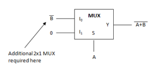
Q : How many 2×1 MUX are required to implement NOR gate?
A : Two 2×1 MUX are required for this operation. The configuration can as follows,

Q : In a 3-bit Johnson’s counter which are the unused states?
A : In a Johnson’s counter, for n bits,
Number of used states = 2n = 6 (for 3 bit counter)
Number of unused states = 2n – 2n = 2 (for 3 bit counter) which are 010 and 101.
Q : How to convert JK flip-flop to D flip-flop?
A : Connect D to J and D’ to K in JK flip-flop. This will make D flip-flop.
Hope this helps you!
Discover more from VLSIFacts
Subscribe to get the latest posts sent to your email.