Matrix multiplication is the computational backbone of neural networks and AI accelerators. In this article, we’ll walk through a practical implementation of a simple Matrix Multiply Unit (MMU) in Verilog, and show you how to verify its functionality using a testbench. Whether you’re a student learning digital design or an engineer prototyping AI hardware, this hands-on guide will help you bridge theory and practice.
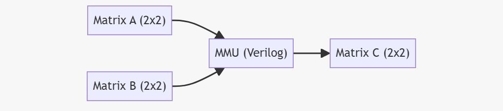
MMU Architecture Overview
To keep things simple, we’ll design an MMU that multiplies two 2×2 matrices. This example is easy to follow, but the same principles scale to larger matrices.
Verilog Implementation of MMU
Here’s the Verilog module for multiplying two 2×2 matrices:
module mmu_2x2 (
    input  [7:0] a00, a01, a10, a11, // Matrix A elements
    input  [7:0] b00, b01, b10, b11, // Matrix B elements
    output [16:0] c00, c01, c10, c11 // Matrix C elements (result)
);
    assign c00 = a00 * b00 + a01 * b10;
    assign c01 = a00 * b01 + a01 * b11;
    assign c10 = a10 * b00 + a11 * b10;
    assign c11 = a10 * b01 + a11 * b11;
endmodule
Explanation:
- Each output element follows the standard matrix multiplication rule:
C[i,j] = \sum_{k} A[i,k] \times B[k,j]- Inputs are 8-bit wide for simplicity; outputs are 17-bit to avoid overflow.
- This is a combinational design—no clock or pipeline yet.
Verilog Testbench for MMU
Let’s verify our MMU with a testbench that applies known inputs and checks the outputs.
module tb_mmu_2x2;
    reg  [7:0] a00, a01, a10, a11;
    reg  [7:0] b00, b01, b10, b11;
    wire [16:0] c00, c01, c10, c11;
    // Instantiate the MMU
    mmu_2x2 uut (
        .a00(a00), .a01(a01), .a10(a10), .a11(a11),
        .b00(b00), .b01(b01), .b10(b10), .b11(b11),
        .c00(c00), .c01(c01), .c10(c10), .c11(c11)
    );
    initial begin
        // Test Case 1
        a00 = 1; a01 = 2; a10 = 3; a11 = 4;
        b00 = 5; b01 = 6; b10 = 7; b11 = 8;
        #10;
        $display("C = [%d %d; %d %d]", c00, c01, c10, c11);
        // Expected: [1*5+2*7=19, 1*6+2*8=22; 3*5+4*7=43, 3*6+4*8=50]
        // Test Case 2
        a00 = 0; a01 = 1; a10 = 1; a11 = 0;
        b00 = 1; b01 = 0; b10 = 0; b11 = 1;
        #10;
        $display("C = [%d %d; %d %d]", c00, c01, c10, c11);
        // Expected: [0*1+1*0=0, 0*0+1*1=1; 1*1+0*0=1, 1*0+0*1=0]
        $finish;
    end
endmodule
How the Testbench Works:
- Applies two test cases with known matrices.
- Waits for the outputs to settle, then prints the results.
- You can compare the displayed results with expected values to verify correctness.
Extending the Design
- Scalability: Use generate blocks or nested loops for larger matrices.
- Pipelining: Add registers between stages to pipeline operations for higher throughput.
- Parameterization: Make matrix size configurable using
parameterfor flexible hardware.
Implementing and verifying a Matrix Multiply Unit in Verilog is a foundational exercise for anyone interested in AI hardware. With this example, you can experiment, extend, and integrate MMUs into more complex accelerators. Verification with a testbench ensures your design is robust and ready for real-world AI workloads.
Discover more from VLSIFacts
Subscribe to get the latest posts sent to your email.